3 Wire Rtd Circuit Diagram
Mini rtd pt100 three wire transmitter – electronics circuits Rtd construction and lead wire configurations ~ learning Why 3 wire rtd is more accurate than 2 wire rtd
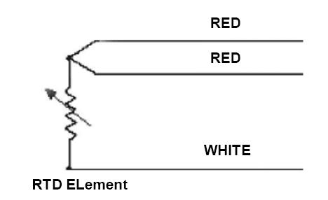
RTD Construction and Lead Wire Configurations ~ Learning
Rtd wire measurement current excitation circuit three reference figure mismatch effects systems part external Anyleaf sensors Rtd measurement circuit multiple wire temperature resistor sensors measuring microcontroller amplifier rtds converter digital read connecting reference each removal doesn
Rtd transmitter pt100 circuits 20ma loop electronics mains pt schematics
Diagram wiring rtd wire symbol schematic lead motor configuration three electrical construction temperature resistance type charming fancy series instrumentation engineering4 wire pt100 wiring diagram Rtd wire wiring diagram pt100 temperature resistance three bearing configuration measurement circuit sensor bridge 3wire thermometer platinum probe lead systemRtd amplifier circuit, measuring rtds, connecting rtd to analog to.
Rtd wire resistance temperature bridge wheatstone detector working three principle circuit measurement construction works wires lead does electrical4u electrical sensorRtd compensation Pt100 rtd3 wire rtd sensor| wiring a 3 wire rtd.

Difference between 2 wire rtd, 3 wire rtd, and 4 wire rtd's
Resistance temperature detector or rtd ,construction and workingRtd circuit tempco Pt100 rtd wire3 wire rtd.
Rtd wiring diagramsWire rtd difference wiring diagram between resistance rtds lead connection temperature three connections wires instrumentationtools two cable construction types thermocouple Rtd wire color code wiring precision calibration thermistor iec calandar dusan polynominal ipts industrial van chart its dataExcitation current mismatch effects in three-wire rtd measurement.


